
How Heat Exchanger Corrosion Actually Happens
By the time a tube starts weeping at a rolled joint, the decision was made weeks or months earlier. Tube corrosion in a heat exchanger is not random decay; it is a circuit that closes on itself whenever four conditions line up on a wetted surface. Every lever you can pull, from cooling water chemistry to tube sheet design, acts on one leg of that circuit. Understand the cell, and you can predict where tubes will fail and how long they will last.
The Electrochemical Cell
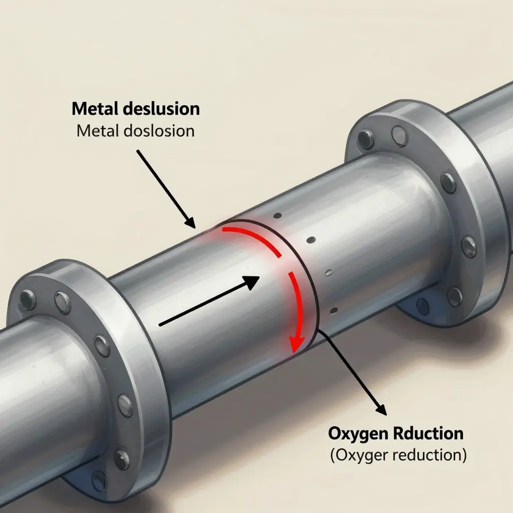
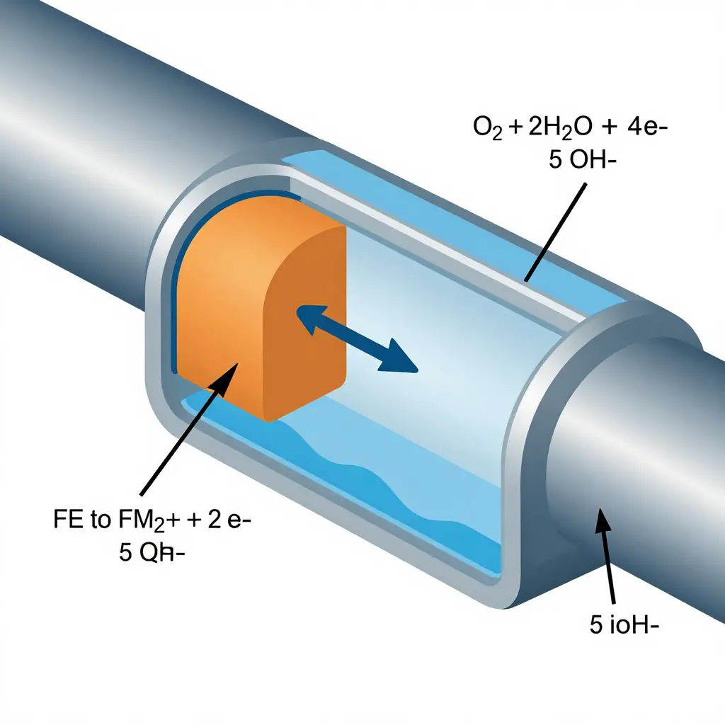
Corrosion needs four connected elements to run. The anode is where metal dissolves: Fe -> Fe2+ + 2e-. The cathode is where an oxidizer is reduced. The electrolyte – your cooling water – carries ionic current between them, and the metallic path carries electrons. In a cooling water circuit the dominant cathodic reaction is oxygen reduction: O2 + 2H2O + 4e- -> 4OH-.
Break any leg and the reaction stalls. Deaeration, chemical inhibitors, coatings, and material selection all work the same way: each interrupts the same loop.
What Each Variable Does
- Oxygen. The primary cathodic depolarizer. Remove dissolved oxygen and the driving voltage collapses, which is why deaerated closed loops corrode far more slowly than open cooling towers.
- Dissolved ions. Chlorides and sulfates raise conductivity and attack protective oxide films. Chloride is the classic trigger for pitting corrosion.
- Temperature. Reaction rates roughly double for every ~10 degrees C rise. Hot tube walls corrode faster and hold less dissolved oxygen, which shifts the balance of the cell.
- Flow velocity. Too slow and deposits form and shield surfaces; too fast and the protective film is torn away mechanically.
General vs. Localized Attack
The mode matters more than the rate. Uniform thinning is slow, predictable, and easy to monitor. Localized attack concentrates the same electrochemical energy into a small area and drills through a wall in a fraction of the time.
| Mode | Trigger | Typical location |
|---|---|---|
| General corrosion | Uniform water chemistry | Whole wetted surface |
| Pitting corrosion | Chlorides, oxidizing conditions | Random spots, stagnant zones |
| Crevice corrosion | Restricted electrolyte exchange | Gaskets, tube-tube sheet gaps |
| Galvanic corrosion | Two dissimilar metals, one electrolyte | Dissimilar tube/header joints |
| Erosion-corrosion | High velocity, entrained solids | Inlet ends, tube bends |
| Under-deposit corrosion | Scale or biofilm blanket | Low-velocity, deposit-prone tubes |
Two of these deserve a closer look. Galvanic corrosion appears when two different metals share an electrolyte – a stainless tube in a carbon steel tube sheet, for example – creating a fixed anode and cathode that never switch roles. Under-deposit corrosion hides beneath scale, where oxygen and ions can no longer equilibrate and a differential aeration cell forms.
The Consequence for Service Life
This is why “how long will this exchanger last?” has no single answer. A clean, deaerated loop with controlled cooling water chemistry and matched materials may deliver decades of general corrosion. The same exchanger with chlorides, deposits, and a bimetallic joint can pit through a tube wall in months. General corrosion gives you warning and time; the localized modes give you a pinhole and a shutdown.
The practical move is to think in terms of failure mode, not just corrosion rate. The chemistry control and tube sheet geometry discussed later build on this cell, and every control point is an argument aimed at one leg of the circuit.
Cooling Water Chemistry: The Silent Driver of Heat Exchanger Corrosion
Every heat exchanger is a controlled experiment in corrosion. The tubes, the shell, and the water moving between them are constantly negotiating a balance between a protective oxide film and the chemistry that dissolves it. Get the cooling water chemistry right, and a unit runs for decades. Get it wrong, and you are buying replacement bundles on a five-year cycle. The parameters below decide which outcome you get.
pH: The Master Variable
pH sets the tone for nearly everything else. Carbon steel builds its best protective film in mildly alkaline water, so most open recirculating systems are held between pH 7.5 and 9.0. Below about 6.5, that film dissolves faster than it can rebuild, and general corrosion rates climb steeply. Above about 10, scale deposition accelerates, and in concentrated caustic conditions cracking becomes a risk. The classic response is a U-shaped curve, with the low point in the middle of the control range.
Conductivity and Dissolved Solids
Conductivity is a proxy for total dissolved ions and the best real-time indicator of how concentrated the water has become. More ions carry more current, which accelerates galvanic and electrochemical attack. A rising trend also signals that you are pushing the cycle of concentration too hard.
Dissolved Oxygen
Oxygen cuts both ways. Some is needed to build and maintain the passive oxide layer, but excess dissolved oxygen drives the cathodic reaction that powers corrosion, particularly pitting and oxygen-cell attack under deposits. Closed hot-water loops run with oxygen scavengers and low dissolved oxygen. In open cooling towers you cannot eliminate oxygen, so you control its effects through chemistry and flow.
Chlorides
Chlorides are the most aggressive common anion in cooling water. They penetrate and break down passive films on stainless steel, starting pitting and crevice corrosion. Even 200 to 300 ppm can be a problem for 304 stainless under stagnant or deposit-covered conditions; 316 grades tolerate somewhat more. Above the material’s critical threshold, pitting can perforate a tube wall in months.
Hardness and Alkalinity: The Langelier Saturation Index
Calcium hardness and alkalinity together determine whether the water deposits scale or dissolves metal. The Langelier Saturation Index (LSI) captures that balance in one number: LSI = pH minus the saturation pH (pHs). A positive LSI means the water is supersaturated and tends to form scale; a negative LSI means it is under-saturated and tends to be corrosive; near zero means it is roughly balanced. Operators aim for a slightly positive LSI, often +0.5 to +1.0, to lay down a thin protective calcium carbonate film without building insulating deposits.
Cycle of Concentration
As water evaporates in a cooling tower, dissolved solids stay behind and concentrate. The cycle of concentration is the ratio of a dissolved solid’s level in the circulating water to its level in the makeup water. Running more cycles saves water and blowdown cost, but it multiplies chlorides, hardness, and conductivity, raising both scaling and corrosion risk. Every water treatment program is balancing that trade-off.
Suspended Solids
Suspended solids settle as deposits on hot tube surfaces. Under those deposits, oxygen and chloride concentrations shift, creating differential aeration cells and crevice environments where corrosion concentrates. Deposits also choke flow and reduce heat transfer, so they cause mechanical and thermal problems alongside corrosion.
Microbiological Activity
Bacteria, algae, and fungi do more than foul surfaces. Sulfate-reducing and iron-related bacteria generate corrosive metabolites and create local acidic, oxygen-depleted zones beneath biofilms. Microbiologically influenced corrosion can pit tubes aggressively even when the bulk water chemistry looks acceptable.
The Parameters Together
| Parameter | Problem Trigger | Primary Risk | Typical Outcome |
|---|---|---|---|
| pH | Below 6.5 or above 10 | Film dissolution / scale and caustic attack | General corrosion or cracking |
| Conductivity | Rising trend | Ionic current, over-concentration | Accelerated galvanic attack |
| Dissolved oxygen | Above 1 ppm in hot loops | Cathodic depolarization | Pitting, oxygen-cell attack |
| Chlorides | Above 200-300 ppm (304 SS) | Passive film breakdown | Pitting and crevice corrosion |
| Hardness / alkalinity | LSI far from zero | Scale or aggressive water | Insulating scale or metal loss |
| Suspended solids | Above ~10-20 ppm | Deposit formation | Crevice and under-deposit pitting |
| Microbes | Visible biofilm | Metabolic acids | Microbiologically influenced pitting |
One number rarely causes trouble on its own. Heat exchanger corrosion is usually the result of several parameters drifting together outside their windows. Watch pH, conductivity, and the LSI daily, keep chlorides and oxygen in check, and let a disciplined water treatment program hold the system inside its safe band.
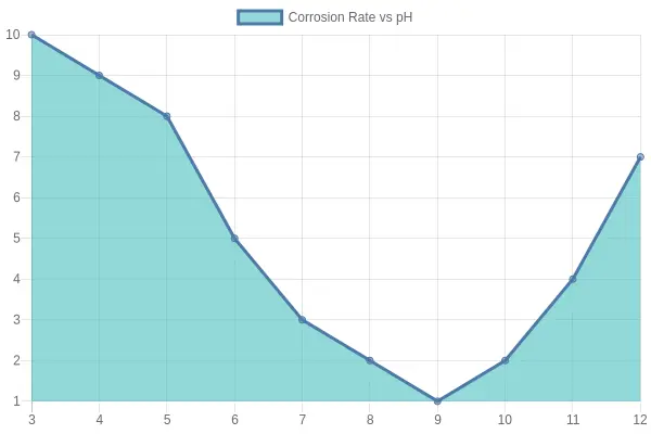
The chart above shows the characteristic U-shaped pH response: corrosion rises in acidic water, bottoms out in the mildly alkaline control range, and climbs again under strongly caustic conditions.
Cooling Water Parameters and Their Corrosion Impact
Cooling water chemistry is the biggest single lever on heat exchanger service life, because small shifts in a few parameters decide whether tubes last five years or twenty-five. The table maps the variables that most directly drive corrosion and fouling, with the thresholds engineers typically watch.
| Parameter | Typical Risk Threshold | Corrosion or Fouling Effect | Recommended Mitigation |
|---|---|---|---|
| pH | < 6.5 or > 9.0 | Acid attack at low pH; scale deposition at high pH | Dose caustic or acid; hold 7.5-9.0 |
| Chlorides | > 200 ppm (SS); > 500 ppm (CS) | Pitting; chloride stress corrosion cracking | Limit blowdown TDS; add inhibitors; upgrade alloys |
| Dissolved Oxygen | > 20 ppb (closed loop) | General corrosion; deep pitting | Deaeration and oxygen scavengers (closed loops) |
| Hardness | > 200 ppm as CaCO3 | Scale fouling; under-deposit corrosion | Softening; scale inhibitors |
| Conductivity | > 3000 uS/cm (TDS proxy) | Galvanic and general corrosion | Tighten blowdown; monitor cycles |
| Suspended Solids | > 10 ppm | Deposit fouling; erosion-corrosion | Filtration; sidestream filters |
| Microbiological Activity | > 10^4 CFU/mL | Biofilm; microbiologically influenced corrosion (MIC) | Biocide program; periodic cleaning |
Treat this table as a control dashboard. Inside these windows, corrosion has little to work with. Outside them, no tube sheet design will rescue the unit.
Best Practices for Controlling Heat Exchanger Corrosion
Turning corrosion theory into uptime comes down to routine discipline. The best-performing plants treat heat exchanger corrosion as a continuously managed process, pairing tight cooling water chemistry control with deliberate tube sheet design and steady monitoring. The checklist below compresses those lessons into ten habits your team can put to work this week.
-
Lock in chemistry targets. Define and post acceptable ranges for pH, conductivity, chloride, and hardness, then track your scaling index (LSI or Ryznar) daily. Drifting chemistry is the most common root cause of premature tube failure.
-
Monitor continuously, not occasionally. Deploy corrosion coupons, linear polarization resistance probes, and online analyzers so excursions surface in hours instead of weeks. Trend the readings and alert on the rate of change – the value of continuous monitoring lies in catching trends early, before damage compounds.
-
Filter and pretreat makeup water. Add side-stream or full-flow filtration to strip suspended solids before they settle on tube walls and seed under-deposit corrosion. Softening or demineralizing makeup water protects the metal downstream as well.
-
Dose chemicals precisely. Automate injection of scale inhibitors, dispersants, and biocides, and calibrate the pumps on a fixed schedule. Manual dosing invites the swings that break protective films.
-
Respect velocity limits. Keep tube-side and shell-side flow inside their design ranges: too slow lets solids drop out, too fast erodes protective oxide layers. Balance flow so every pass stays in the sweet spot.
-
Protect equipment during shutdowns. Apply nitrogen blankets, dry-air purging, or inhibited wet layup whenever a unit sits idle. Stagnant, oxygen-rich water is a corrosion accelerator, not a safe resting state.
-
Inspect and clean on schedule. Pull bundles, hydro-blast tubes, and log wall-thickness readings at a set interval. Consistent records turn small deviations into early warnings instead of surprises.
-
Design for drainage and access. Specify generous clearances, sloped shells, and removable heads so crews can clean quickly and water cannot pool. Smart tube sheet design reduces both corrosion risk and maintenance downtime.
-
Match metallurgy and coatings to the duty. Upgrade to higher-alloy tubes, tube sheets, or protective coatings where chemistry alone cannot hold the line. These retrofits often pay back within a few operating years.
-
Train operators and keep logs. Make chemistry rounds and probe data part of every shift handover, and give teams the authority to act on alarms. Informed operators catch problems long before they become failures.
None of these steps is exotic, and each one costs far less than a single unplanned outage. Start with the two or three that address your worst offenders, document what changes, and expand from there. Controlled cooling water chemistry, thoughtful tube sheet design, and steady monitoring together decide whether a heat exchanger lasts five years or twenty-five.
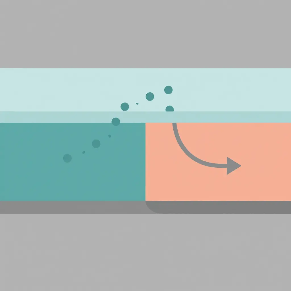
The diagram above breaks down the four essentials of any electrochemical corrosion cell on a metal surface: an anode region where metal dissolves, a cathode region where the reduction reaction consumes electrons, an ion-conducting electrolyte layer that carries charge between them, and a continuous electron path through the metal itself. Remove any one of these four elements and the corrosion loop stalls. That is why cooling water chemistry and tube sheet geometry matter so much: they influence how, and how aggressively, the circuit completes itself.
Tube Sheet Design and Its Role in Service Life
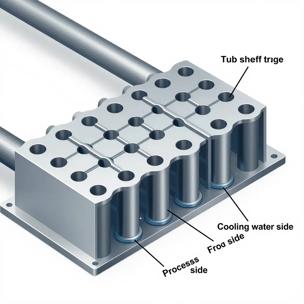
Most heat exchangers do not fail because the tubes themselves were too thin. They fail because the metal around them gave up first. Understanding tube sheet design is really about where a unit fails first, and whether you get four years or twenty out of it.
Geometry Is a Corrosion Variable
Corrosion is often treated as a purely chemical problem – dissolved oxygen, chlorides, pH, and flow rate. But the tube sheet is where chemistry meets mechanical geometry, and that geometry can make an aggressive environment worse. A poorly chosen material, a tight ligament, or a rough rolled joint does not create corrosion; it concentrates it. The cooling water decides how corrosive the environment can be, while tube sheet design decides how much of that potential the metal actually experiences.
Material Selection: The First Line of Defense
The tube sheet must survive both the cooling water side and the process side, often in the same plate. Common choices illustrate the trade-offs:
| Material | Corrosion Resistance | Typical Use | Watch Out For |
|---|---|---|---|
| Carbon steel | Low | Clean, treated water | Generalized thinning, galvanic coupling |
| 316L stainless | Moderate-High | Chloride-limited cooling water | Pitting, crevice attack |
| Duplex stainless | High | Seawater, brackish water | Welding controls |
| Titanium | Very high | Aggressive seawater | Cost, galvanic driving force |
When a titanium or stainless tube sheet is paired with carbon steel tubes, the metals form a galvanic couple in conductive cooling water. The more noble sheet drives the less noble tube to corrode faster at the connection point.
Thickness, Ligaments, and Localized Attack
Tube sheet thickness is usually set by pressure, but the ligament width – the strip of metal between adjacent tube holes – controls how long it survives. A narrow ligament concentrates stress and heat-flux gradients, giving localized attack a natural starting point. Wider ligaments spread that load and slow crevice development.
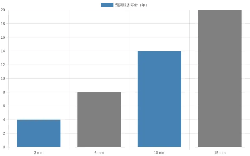
The trend reflects field experience: doubling the ligament can more than double service life, because corrosion damage scales with how tightly the environment is squeezed around the joint.
The Tube-to-Tubesheet Joint: Crevices and Connections
The single most failure-prone location in the unit is the tube-to-tubesheet joint. Three configurations are common, and each carries its own risk:
- Rolled (expanded) joints – mechanically expanded into the hole. Reliable, but they leave a crevice at the back wall where stagnant water concentrates chloride and microbes.
- Welded joints – a fusion seal eliminates the crevice but introduces a heat-affected zone with its own sensitivity to stress corrosion cracking.
- Rolled and welded (hybrid) – combines strength with a sealed crevice, and is the preferred choice for chloride-heavy cooling water.
Crevice formation is the core mechanism here. Inside that narrow gap, oxygen is depleted, pH shifts, and chloride concentrates far above the bulk water. That trapped chemistry turns an otherwise acceptable heat exchanger corrosion risk into pitting and under-deposit attack.
Hole Geometry as a Trigger
Tube hole geometry shapes everything downstream. Oversized or oval holes give the joint too little interference, so expansion is uneven and residual crevices remain. Rough or scored hole walls create micro-crevices that seed pitting. Sharp transitions and burrs act as stress raisers. Each one turns a tube sheet design detail into a corrosion initiation site.
Flow Distribution: The Hidden Variable
Uneven flow distribution is easy to overlook. Poor baffling or a clogged inlet sends more cooling water – and more oxygen and velocity – across certain tubes, accelerating erosion-corrosion there while other zones sit stagnant and collect deposits. Even a perfectly machined tube sheet suffers if the flow across it is unbalanced.
Design Rules for Service Life
Service life is largely set at the drawing board, not in the water. For cooling water that threatens heat exchanger corrosion:
- Match tube sheet material to the actual water chemistry, not just the spec sheet.
- Keep ligaments wide enough to spread stress and heat flux.
- Prefer rolled-and-welded tube-to-tubesheet joint designs in aggressive or chloride-bearing water to close the crevice.
- Control hole geometry – tight tolerances, smooth walls, no burrs – so joints start clean.
- Design for even flow so no tube becomes a sacrificial zone.
Treat the tube sheet as a design decision rather than a fixed part number, and service life becomes something you control instead of a surprise you inherit.
Heat Exchanger Service Life vs. Cooling Water Chemistry and Tube Sheet Design
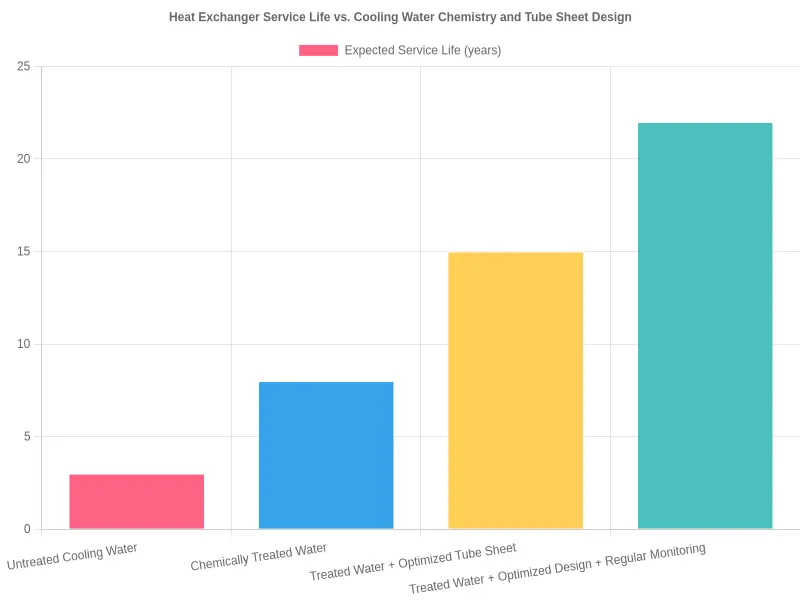
Each layer of protection compounds the last. Chemical water treatment roughly triples tube life over raw water, an optimized tube sheet adds several more years by eliminating crevice corrosion and flow dead zones, and pairing that design with routine monitoring stretches service life toward its practical maximum of about 22 years.
Material Selection: Matching the Alloy to the Water It Meets
A heat exchanger corrosion problem is a conversation between the metal and the water touching it, and material selection decides how that conversation ends. Get it right and the unit runs for decades; get it wrong and you are re-tubing every five years. The reasoning below moves from raw material properties to practical suitability, tied back to cooling water chemistry and tube sheet design.
Carbon Steel: The Budget Baseline
Carbon steel is cheap, strong, and easy to fabricate. What it lacks is protection. It offers almost no resistance to chloride attack, so it survives only in clean, treated, closed-loop water with tight pH control and corrosion inhibitors. In an open cooling tower loop, pitting begins quickly and wall loss becomes a routine maintenance item.
Stainless Steel: 304, 316, and Duplex
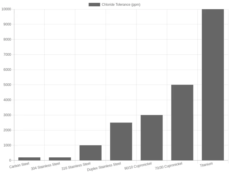
304 stainless steel depends on a chromium oxide film that breaks down once chlorides climb above roughly 200 ppm, inviting pitting and crevice corrosion. 316 stainless steel adds molybdenum, pushing tolerance toward 1,000 ppm, which makes it the workhorse for moderately aggressive cooling water. Duplex stainless steel combines austenitic and ferritic structure, delivering higher strength plus strong resistance to chloride stress corrosion cracking, which suits higher-chloride, higher-temperature duty.
Copper Alloys: Admiralty and Cupronickel
Admiralty brass historically handled brackish water, but it is sensitive to ammonia and to erosion at high velocity. 90/10 cupronickel and 70/30 cupronickel resist seawater far better, form protective films, and help deter biofouling. Both dislike sulfide-laden or ammonia-polluted water, so check the chemistry before you commit.
Titanium: The Seawater Champion
Titanium is effectively immune to chloride attack across normal ranges and tolerates far more than 10,000 ppm chloride. The trade-offs are cost and a strongly noble galvanic position, which can accelerate corrosion of any carbon steel component it touches unless dielectric isolation is designed in.
Coated Options
Epoxy, phenolic, and polymer coatings act as a low-cost barrier for carbon steel. They work only while intact: a single holiday concentrates attack into deep pits that are hard to find before failure.
| Material | Chloride Tolerance | Pitting / Crevice Resistance | Galvanic Risk | Typical Service Life |
|---|---|---|---|---|
| Carbon steel | Moderate (~500 ppm) | Low (general corrosion dominates) | Moderate | 5-10 years |
| 304 stainless steel | Low (~200 ppm) | Moderate | Low-Moderate | 10-15 years |
| 316 stainless steel | Good (~1,000 ppm) | High | Low-Moderate | 15-20 years |
| Duplex stainless steel | Very good (~2,500 ppm) | Very high | Low-Moderate | 20-25 years |
| Admiralty brass | Moderate | Moderate | Low | 10-15 years |
| 90/10 cupronickel | High (~3,000 ppm) | High | Low | 15-20 years |
| 70/30 cupronickel | Very high (~5,000 ppm) | Very high | Low | 20-30 years |
| Titanium | Excellent (>10,000 ppm) | Excellent | High (with steel) | 30+ years |
Galvanic Effects and Tube Sheet Design
Mixing metals on a shared tube sheet creates a galvanic couple, and the more active material becomes the anode and corrodes faster. Rolled joints, baffle clearances, and stagnant crevices at the tube sheet are where chloride attack and galvanic effects concentrate. Material selection therefore has to be matched to tube sheet metallurgy, with insulator sleeves, coated tube sheets, or sacrificial anodes to break the circuit.
Water Chemistry and Service Life
Chloride level, pH, temperature, and flow velocity decide everything. The chart above shows how widely chloride tolerance varies from alloy to alloy. Choose a material whose ceiling sits comfortably above your worst-case water chemistry, verify the tube sheet pairing, and you can stretch service life from a few years to several decades. When in doubt, confirm real water analysis before the order is placed, not after the first pinhole leak.
The values shown are illustrative engineering guidelines. Always confirm final material choices with your water chemistry analysis and a qualified corrosion engineer.
Water Treatment and Monitoring Strategies That Extend Heat Exchanger Service Life
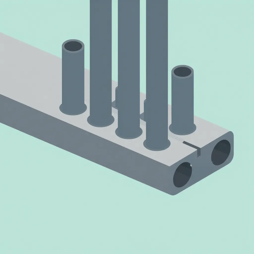
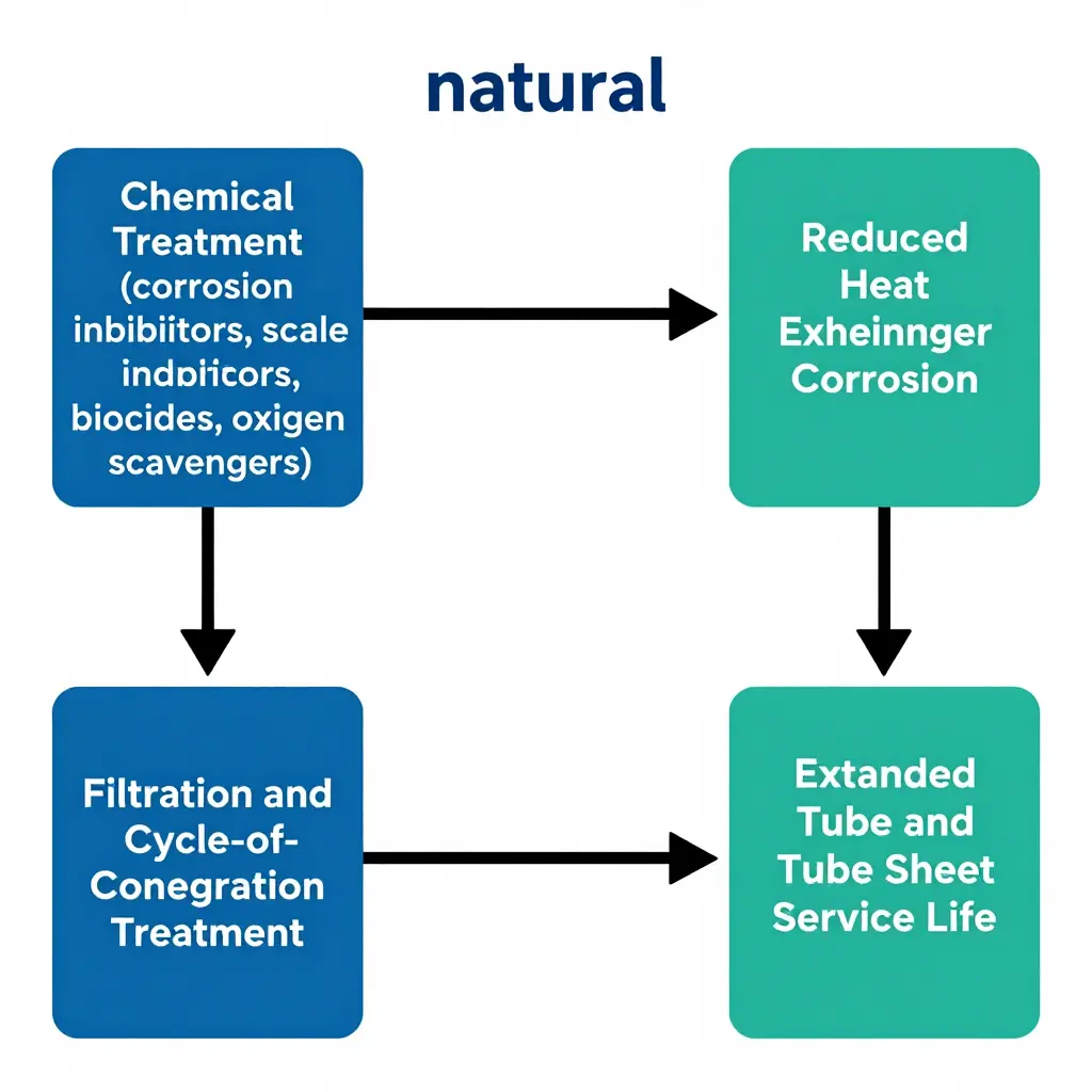
A heat exchanger rarely fails because the water is “dirty.” It fails because the wrong dissolved ions, suspended solids, and microbes are allowed to sit against metal for months on end. When cooling water chemistry stays inside its target envelope, corrosion, scaling, and fouling lose their grip on the tubes and tube sheet. The chain is simple: a deliberate treatment action changes the water, cleaner water reduces heat exchanger corrosion, and lower corrosion means longer, safer service life.
Chemical Treatment: The First Line of Defense
A well-built water treatment program starts with chemistry. Corrosion inhibitors form a thin protective film on carbon steel and admiralty brass, slowing the electrochemical reaction that eats tube walls. Scale inhibitors keep calcium carbonate dissolved so it cannot crystallize onto hot tube surfaces, where heat flux accelerates deposition. Biocides control the bacteria and algae that create biofilms, which both insulate the metal and shelter corrosive organisms underneath. Oxygen scavengers strip out dissolved oxygen that would otherwise drive pitting.
Each dosing decision is anchored to cooling water chemistry targets – pH, conductivity, and inhibitor residuals – that engineers set in advance. Drifting past those targets, by over-dosing or neglect, wastes money and can trigger corrosion on its own.
Filtration and Side-Stream Treatment
Full-flow and side-stream filtration pull suspended solids out of the loop before they settle on the tube sheet or plug tube inlets. A well-sized side-stream filter usually turns over one to five percent of circulating flow, continuously scrubbing the system. This matters most where tube sheet design leaves tight lanes between tubes: a lodged deposit narrows flow, raises local velocity, or creates a stagnant pocket, and any of those starts a corrosion cell.
Cycle-of-Concentration Control
Every evaporation cycle concentrates dissolved solids. Too few cycles waste water; too many push conductivity and hardness past the point where scale and corrosion take hold. Bleed or blowdown control holds the cycle of concentration at the value the cooling water chemistry targets allow, balancing water efficiency against tube protection.
Monitoring: What You Do Not Measure, You Cannot Fix
Monitoring turns a treatment program from guesswork into management. Water sampling tracks pH, conductivity, inhibitor residual, and microbiological counts against targets. Corrosion coupons and electrochemical probes measure actual metal loss and confirm the chemicals are earning their keep. Tube inspection with eddy current or borescope tools reveals pitting, scaling, and under-deposit attack before a leak forces an unplanned outage. Think of it like a motorcycle tire pressure monitoring system that flags small problems before they become blowouts: the value is in catching the trend early, not reacting to the failure.
| Parameter | Typical Target Range | Monitoring Frequency |
|---|---|---|
| pH | 7.5 – 9.0 | Daily |
| Conductivity | Set by cycle-of-concentration limit | Daily or continuous |
| Corrosion inhibitor residual | Per supplier specification | Daily |
| Total suspended solids | < 10 mg/L | Weekly |
| Microbiological count | < 10,000 CFU/mL | Weekly |
| Corrosion coupon rate | < 2 – 3 mpy | Monthly |
A practical rhythm keeps it manageable: daily sampling, weekly coupon checks, and periodic inspections scheduled around tube sheet design constraints so the hardest-to-reach lanes get examined too.
From Treatment to Extended Service Life
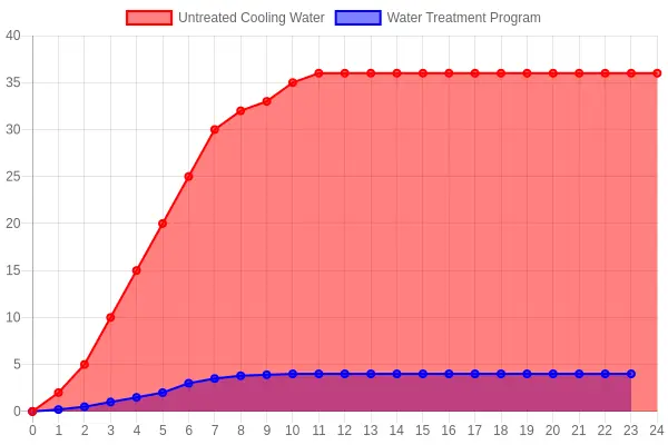
The logic loops back on itself. Consistent chemical dosing, clean side-stream water, and disciplined blowdown keep cooling water chemistry on target. On-target chemistry suppresses heat exchanger corrosion at its source. Lower corrosion preserves wall thickness on the tubes and tube sheet, stretching the interval between repairs and replacements from a few years to a decade or more.
Good water treatment is the cheapest way to keep tube walls intact.
What the Breakdown Tells Us
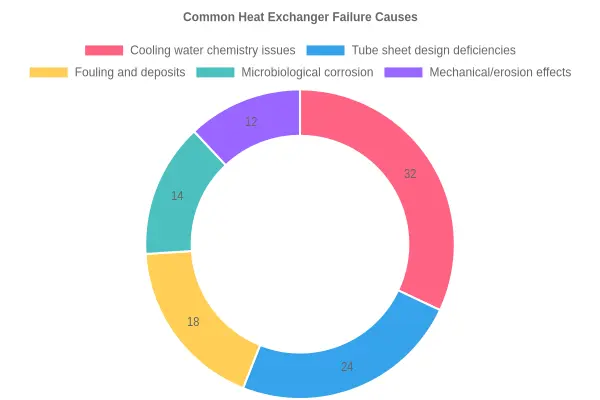
The chart shows that cooling water chemistry issues (32%) and tube sheet design deficiencies (24%) together account for more than half of all heat exchanger failures, which supports the two themes at the heart of this article. Fouling and deposits (18%), microbiological corrosion (14%), and mechanical or erosion effects (12%) round out the picture, and they usually compound the underlying chemistry and design problems rather than acting alone. Getting water treatment right and engineering the tube sheet for real-world conditions delivers the biggest return on reliability investment; mechanical and microbiological damage tends to follow where those two foundations are weak.
Inspection and Diagnosis: Catching Heat Exchanger Corrosion Before It Costs You
Diagnosing a Trend, Not a Failure
By the time a heat exchanger leaks, weeps at a rolled joint, or loses thermal efficiency, most of its useful life is already spent.
The real job of inspection is not to confirm a failure – it is to measure the rate of degradation while there is still time to adjust cooling water chemistry or correct a design weakness.
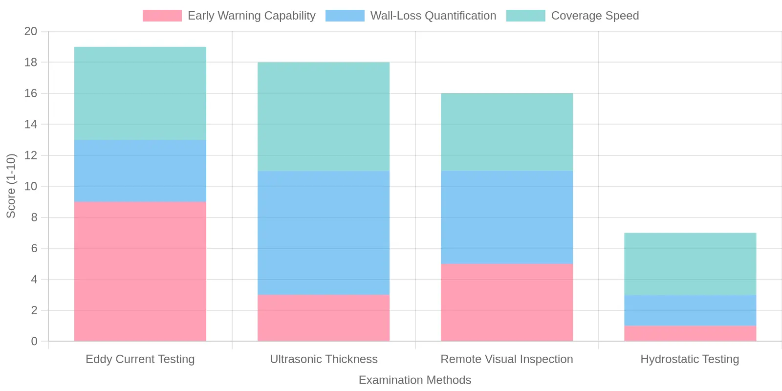
The methods below are ordered by how early they give warning, and by what each one can quantify.
Eddy Current Testing: The Earliest Warning Signal
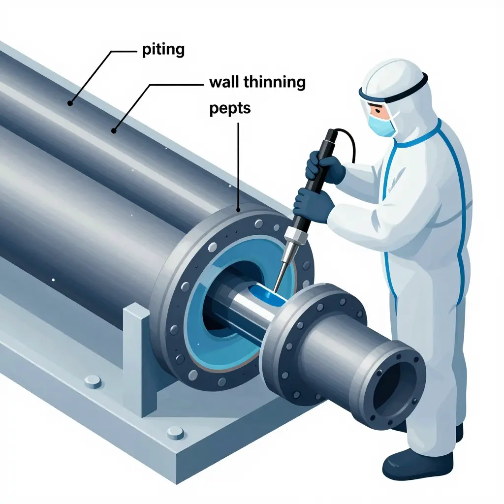
Eddy current testing buys the most warning time. It detects wall thinning, pitting, and cracking from inside the tube without cutting anything open.
An electromagnetic probe induces currents in the tube wall; corrosion defects distort those currents, and the resulting signal maps localized loss along the full length of a tube. A baseline eddy current survey followed by periodic re-tests reveals corrosion velocity, which lets you project remaining service life with real numbers.
Ultrasonic Thickness Measurement: Quantifying What Remains
Where eddy current estimates, ultrasonic thickness measurement confirms. It gives you a hard number for the remaining wall.
By comparing measured thickness against the original specification, engineers calculate the corrosion allowance consumed and the annualized metal-loss rate. That is the number that drives retirement and re-tubing decisions.
Remote Visual Inspection: Reading the Pattern
Remote visual inspection explains why the numbers look the way they do. A borescope or camera crawler reveals pitting morphology, scaling, biofilm, and under-deposit corrosion that thickness gauges can miss.
Seeing the pattern – pitting beneath deposits, preferential attack near inlet ends – points straight back to a cooling water chemistry imbalance or a flow-distribution problem.
Hydrostatic Testing: Confirmation, Not Discovery
Hydrostatic testing is the final check, not the early alarm. Pressurizing the shell or tube side and watching for leaks confirms integrity at a point in time.
It is valuable for validating repairs and meeting code, but it cannot quantify wall loss, so it should never be your primary corrosion-monitoring tool.
Matching the Method to the Indicator
| Method | Best For | Primary Indicator | Limitation |
|---|---|---|---|
| Eddy current testing | Tube wall integrity | Wall thinning, pitting, cracking | Needs clean tubes, skilled analyst |
| Ultrasonic thickness | Localized wall loss, headers | Remaining thickness, corrosion rate | Point-by-point, slower coverage |
| Remote visual inspection | Surface condition | Pitting, fouling, biofilm, cracks | Surface only, no wall depth |
| Hydrostatic testing | Integrity confirmation | Leaks, joint failures | No early warning |
Closing the Loop: From Findings to Chemistry and Design
Inspection data is only valuable when it changes something. Two feedback loops matter most.
The first feeds cooling water chemistry. Rising pitting counts or chloride-driven attack on re-test mean the corrosion inhibitor dose, pH target, or blowdown schedule is failing and has to be corrected at the source.
The second feeds tube sheet design decisions. If eddy current maps show repeat failures near the tube sheet, the fix may be a revised tube-to-tubesheet joint, better inlet impingement protection, or a materials upgrade.
When these loops run continuously, heat exchanger corrosion stops being a surprise and becomes a managed variable, and service life moves from a hope to a calculated outcome.
Frequently Asked Questions About Heat Exchanger Corrosion
Heat exchanger corrosion raises a lot of practical questions for the engineers, maintenance crews, and facility managers who keep process equipment running. The answers below cover the questions we see most often, and each one stands on its own so you can scan straight to the topic you need.
How does cooling water chemistry affect heat exchanger corrosion?
Cooling water chemistry is the biggest single driver of tube and shell degradation. Parameters such as pH, dissolved oxygen, chloride concentration, conductivity, and suspended solids all affect how aggressively the water attacks metal surfaces. Water that sits below roughly pH 6.5 accelerates general wastage, while high dissolved oxygen feeds pitting and crevice attack. When conductivity climbs, the water carries more ions and becomes a better electrolyte, so galvanic and electrochemical cells form more readily. Controlling cooling water chemistry through filtration, chemical dosing, and blowdown management directly slows heat exchanger corrosion and stretches the interval between repairs. Ignoring it is the fastest way to convert a healthy unit into a recurring maintenance headache.
Why does tube sheet design matter for service life?
The tube sheet is where tubes, shell, and channels meet, which makes it the most stressed joint in the whole exchanger. Poor tube sheet design traps stagnant water, creates crevices, and concentrates stress at the tube-to-tubesheet roll or weld. Those conditions invite crevice corrosion and stress corrosion cracking long before the tubes themselves show problems. A well-designed tube sheet promotes even flow distribution, minimizes dead zones, and allows proper drainage and cleaning access. Thoughtful selection of material, ligament width, and joint geometry means the mechanical and corrosion performance of the unit holds up far longer. Tube sheet design often decides whether an exchanger lasts five years or twenty.
What are the most common corrosion types in heat exchangers?
The usual suspects are uniform (general) corrosion, pitting, crevice corrosion, galvanic corrosion, erosion-corrosion, and stress corrosion cracking. Uniform corrosion thins metal steadily and predictably, which makes it easier to manage. Pitting and crevice corrosion are more dangerous because they bore deep locally with little visible warning. Galvanic corrosion appears when dissimilar metals share an electrolyte, while erosion-corrosion shows up where high-velocity flow scours protective oxide layers. Stress corrosion cracking, often chloride-driven in stainless steels, can fail a tube suddenly. Knowing which mechanism threatens your unit lets you target inspection and treatment where it counts.
How often should heat exchangers be inspected?
There is no universal number, but most operators inspect on a risk-based schedule rather than a fixed calendar. A common baseline is a full internal inspection every 12 to 24 months, with more frequent checks for units handling aggressive chemistry or running at high temperatures. Facilities using corrosion monitoring, water sampling, and performance trending can often extend intervals safely. Watch for warning signs between inspections: rising pressure drop, falling heat transfer efficiency, and cooling water chemistry that drifts out of range. If any of those appear, pull the unit early rather than wait for the next scheduled window.
Which materials resist chloride attack best?
Chlorides are the classic enemy of stainless steels, so material choice matters enormously where chloride levels are high. Titanium and duplex stainless steels offer strong chloride resistance and are common picks for seawater and brackish duties. Super-austenitic and 6% molybdenum alloys handle even harsher chloride environments. For moderate chloride exposure, higher-alloy austenitic stainless steels outperform standard 304 and 316 grades, which are prone to pitting and stress corrosion cracking. Matching the alloy to the actual chloride concentration, temperature, and oxygen level in your cooling water chemistry is the key to avoiding premature failure.
How can I extend service life on a limited budget?
You do not need a capital rebuild to add years to a unit. Start with the cheapest, highest-impact levers: tighten cooling water chemistry control, fix dosing and filtration, and eliminate stagnant flow. Improve tube sheet design details where you can, such as better drainage and access for cleaning, during the next outage. Adopt a risk-based inspection plan so you spend effort on the units most likely to fail. Where a full retube is out of reach, selective tube plugging and targeted coatings can buy time. Finally, keep clean, accurate records of water quality and inspection findings so small trends never become expensive surprises. Discipline in monitoring almost always costs less than emergency replacement.
Does flow velocity really influence corrosion rates?
Yes, and the effect cuts both ways. Too low a velocity lets solids settle and deposits form, creating oxygen concentration cells and under-deposit corrosion. Too high a velocity strips protective films and drives erosion-corrosion, especially at tube inlets and bends. Staying within the design velocity range, and matching it to the alloy’s tolerance, keeps the protective layer intact while preventing fouling. It is one of the few variables you can tune without changing hardware.
Can coatings or linings replace the need for better materials?
Coatings and linings are useful tools, but they are a complement, not a substitute. They can protect carbon steel and prolong life in moderately aggressive service at lower cost than exotic alloys. However, they are vulnerable to damage during cleaning and can hide corrosion underneath if they fail. Use them strategically alongside sound cooling water chemistry and thoughtful tube sheet design rather than as a stand-alone fix.
Conclusion: Chemistry, Design, and Discipline Decide Service Life
Heat exchanger corrosion is rarely the fault of a single variable. More often it is the predictable result of cooling water chemistry and tube sheet design pulling in opposite directions. Aggressive water attacking a poorly matched tube-to-tubesheet joint will shorten service life dramatically, while the same water, properly conditioned and paired with a sound mechanical design, supports reliable operation for decades.
The Four Controls That Matter
The plants that get the longest, most dependable service treat four things as one system instead of four separate departments:
- Cooling water chemistry – hold pH, dissolved oxygen, chlorides, and scaling potential inside defined limits, and correct excursions quickly.
- Tube sheet design – match joint type, ligament width, and flow path to the real water and thermal duty, not to a default drawing.
- Materials selection – choose alloys that suit the water you actually have, not the cleanest water you hope for.
- Monitoring – track corrosion coupons, fouling factors, and water parameters so you catch drift before it becomes a leak.
Priority Actions
For engineers, maintenance professionals, and facility managers, three moves pay off fastest:
- Audit the interface. Review how water-treatment targets line up with the installed tube sheet design and flag any mismatch.
- Set a baseline. Record corrosion rates, water chemistry, and fouling data so every future change can be measured against a known reference.
- Schedule on data. Build corrosion trends into your maintenance plan so replacements and cleanings happen on evidence, not on failure.
The Bottom Line
When cooling water chemistry and tube sheet design are controlled together, corrosion stops being a surprise and becomes a managed variable. That coordination – spanning chemistry, design, materials, and monitoring – is what delivers the longest, most reliable heat exchanger operation, and it is a discipline any well-run facility can build into its routine.