
Heat Exchanger Tube Vibration: Why Baffle Spacing and Flow Velocity Decide Fatigue Life
Heat exchanger tube vibration gets treated as a nuisance more often than it deserves. It is a fatigue failure mode, and two design choices decide how long a bundle lasts: baffle spacing and flow velocity. Each vibration cycle puts stress into the supports and baffle intersections, and that stress draws down the tube’s fatigue life. Nothing shows on the outside until a crack reaches the wall, by which point the damage is years old. These failures follow from the design; they are not random.
Baffle spacing fixes the unsupported span and how far a tube can bend between plates. Flow velocity sets the energy of the crossflow that drives it. Between them they determine whether the motion stays within what a tube tolerates for decades, or builds toward cracking, fretting, and eventual perforation. Change one without rechecking the other, and a fatigue calculation that passed on paper can still fail in service. The two variables are coupled, and treating them as independent is where designs go wrong. Both also set heat transfer and pressure drop, so the remedy is rarely just cutting flow or adding baffles.
This article looks at how the two interact, then sets out what engineers can do about them in new designs and existing units.
The Physics of Tube Vibration: Four Excitation Mechanisms
Tubes rarely fail in one event. They fail from thousands of small oscillations, each one spending a little fatigue life where the tube is restrained. Four excitation mechanisms drive that motion, and each loads the tube-to-tubesheet joints and baffle supports differently. Knowing which one dominates your service conditions is the starting point for setting baffle spacing and allowable flow rates.
Fluid-elastic instability. The most destructive of the four. It begins when shell-side crossflow velocity passes a critical threshold and tube motion starts taking energy out of the flow instead of dissipating it. As the bundle deflects, the flow field shifts with it; once the resulting negative damping outweighs the bundle’s structural damping, amplitude grows instead of settling. The oscillation is self-amplifying, and it hammers the tube-to-tubesheet joints and baffle supports until fatigue cracks open there.
Vortex shedding. Alternating vortices shed from the downstream side of each tube, producing a periodic lift force whose frequency is set by crossflow velocity and tube diameter. When the shedding frequency lands near a tube’s natural frequency, the tube locks in and vibrates at high amplitude even at moderate flows that would otherwise be harmless. Sustained lock-in produces high-cycle alternating stress exactly where the tube is clamped: the baffle supports and the rolled or welded tube-to-tubesheet joint. That is where the first through-wall cracks appear.
Turbulent buffeting. Broadband pressure fluctuations in the shell-side flow cause this one as the fluid churns through the bundle, squeezes through baffle windows, and separates off upstream tubes. Where vortex shedding is narrow-band, buffeting spreads its energy across a wide frequency range and excites many tubes at once rather than one resonant tube. The damage adds up: millions of low-amplitude cycles cause fretting and bending stress at the baffle supports, thinning the wall until a fatigue crack starts.
Acoustic resonance. This occurs when the vortex-shedding frequency coincides with a standing acoustic wave across the shell, so the gas or vapour column amplifies the pressure pulsation rather than damping it. The coupling between bundle and shell cavity can push noise above 120 dB and puts large fluctuating loads on tubes near the shell wall. The excitation is narrow in frequency but distributed across the shell, so peak stresses again land at baffle supports and tube-to-tubesheet joints, speeding up fatigue cracking wherever clearance allows movement.
| Mechanism | Primary Driver | Frequency Character | Where Damage Concentrates |
|---|---|---|---|
| Fluid-elastic instability | Crossflow velocity above critical value | Self-excited, exponentially growing | Mid-span and supports |
| Vortex shedding | Alternating vortex lift on each tube | Narrow-band, lock-in possible | Baffle supports and joints |
| Turbulent buffeting | Broadband shell-side turbulence | Wide-band, random | Baffle supports, fretting zones |
| Acoustic resonance | Shedding frequency matching shell acoustic mode | Narrow-band, high decibels | Tubes near shell wall |
The four rarely act alone; a bundle can shed vortices, buffet, and resonate acoustically in the same operating window. The practical defence is geometry and flow control: spacing that keeps tube natural frequencies clear of the excitation band, lower crossflow velocity, and support placement that shortens the longest spans. Set those at the design stage and the tubes are far less likely to spend their service life cracking.
Baffle Spacing: The Hidden Variable That Decides Tube Fatigue Life
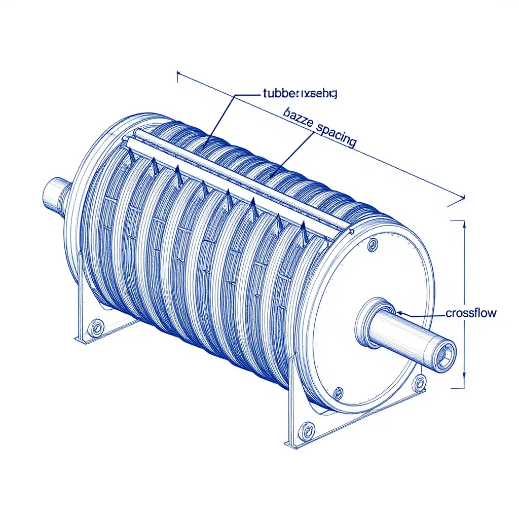
Baffle spacing is the distance between adjacent transverse baffles along a shell-and-tube exchanger. It reads as a minor mechanical detail, but it sets the unsupported span of every tube in the bundle, and that span largely decides whether a tube lasts twenty years or cracks in eighteen months. When a vibration problem has to be fixed, baffle spacing is often the lever that actually moves it.
How Unsupported Span Controls Tube Natural Frequency
A tube behaves like a slender beam pinned between baffles, so its fundamental natural frequency scales roughly with the inverse square of the unsupported span:
fn proportional to (1 / L^2) multiplied by the square root of (EI / m)
Here L is the unsupported span, EI the bending stiffness, and m the mass per unit length. The inverse-square dependence is what makes the relationship so steep: lengthen the span by 50 percent and the natural frequency drops by more than half.
Why Wider Baffle Spacing Pushes You Toward the Excitation Band
A longer unsupported span lets each tube flex more freely, so wider spacing lowers stiffness and the natural frequency drifts down toward the frequencies that shell-side crossflow generates. Vortex shedding and turbulence produce periodic forces whose frequency rises with flow velocity, which makes a soft, low-frequency tube paired with fast crossflow a dangerous combination. When the natural frequency or one of its harmonics matches the shedding frequency, resonance amplifies deflection, and every cycle adds fatigue damage at the tube-to-tubesheet joint.
Why Narrower Spacing Is Not a Free Lunch
The instinct is to tighten the spacing and stiffen everything, and it works: a shorter unsupported span raises the natural frequency. But narrower spacing forces the same shell-side flow through a smaller cross-section, which raises crossflow velocity through the baffle windows and pushes pressure drop up sharply. More baffles also mean more flow reversals and more turbulence, so pumping cost climbs with every plate added.
The Design Trade-Off
There is no single “correct” baffle spacing, only a balance among three demands:
- Heat transfer performance – closer spacing raises velocity and the shell-side heat transfer coefficient, shrinking the surface area required.
- Pressure drop – the same higher velocity inflates pumping power, which can dominate lifecycle cost.
- Vibration integrity – wider spacing drops stiffness and natural frequency into the excitation window; tighter spacing invites velocity-driven excitation and window-zone damage.
What to check before locking in a number:
- Check the ratio of unsupported span to tube diameter, and keep the tube natural frequency well clear of shedding frequencies.
- Screen for fluid-elastic instability by comparing reduced velocity (V/fnD) with the shell-side crossflow velocity.
- Confirm that tube-to-baffle-hole clearance and support type still provide real restraint.
- Verify that the heat-transfer gain justifies the added pressure drop.
| Baffle Spacing | Tube Natural Frequency | Shell-side Pressure Drop | Heat Transfer | Vibration Risk |
|---|---|---|---|---|
| Narrow | Higher (stiffer) | High | High | Velocity-driven, window damage |
| Moderate | Balanced | Moderate | Moderate | Lowest when tuned |
| Wide | Lower (softer) | Low | Low | Resonance / instability prone |
As spacing widens, natural frequency, pressure drop, and heat transfer all fall together, which is why baffle spacing is a trade-off rather than a tuning knob.
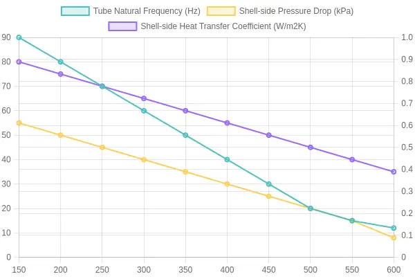
Treat baffle spacing as a vibration parameter first and a thermal one second. Model the unsupported span, compare the natural frequency against every excitation mechanism you can identify, and accept the spacing that satisfies all three constraints. A number chosen purely for heat transfer tends to announce itself later as a cracked tube.
Why Baffle Spacing Sets the Frequency of Your Tubes
Every tube is a beam, and every beam has a natural frequency, the rate at which it prefers to vibrate when nudged. Move the baffles farther apart and you change how well that tube is supported. Fewer supports over a longer span give a floppier tube and a lower natural frequency, which is the wrong direction for it to drift.
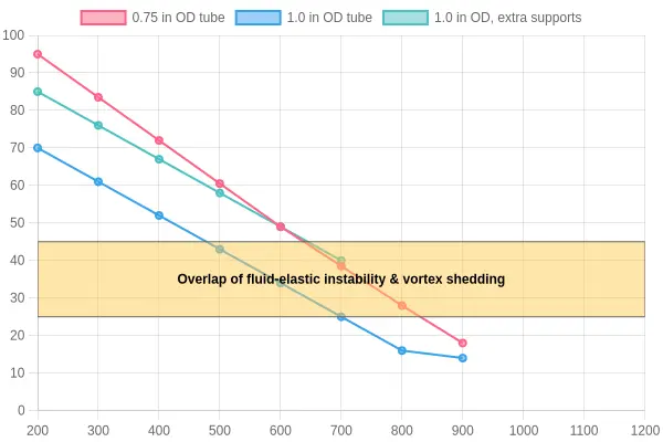
The chart traces the relationship directly. As baffle spacing climbs from 200 mm to 1200 mm, each curve sinks. The thinner 0.75 in OD tube falls fastest, while the 1.0 in OD tube with extra intermediate supports stays highest across the whole range.
Reading the Shaded Band
The amber band spanning roughly 25 to 45 Hz marks the danger zone: the range where vortex-shedding and buffeting forces are concentrated, and where instability-driven motion appears. A natural frequency inside that band is being pushed by more than one mechanism, which is worse than being pushed by one. Wherever a curve dips into the band, the fatigue concern is real, not theoretical.
| Tube / Support Condition | Frequency at 200 mm | Frequency at 1200 mm | Trend |
|---|---|---|---|
| 0.75 in OD tube | ~95 Hz | ~18 Hz | Steepest drop, enters band early |
| 1.0 in OD tube | ~70 Hz | ~14 Hz | Drops through band by ~700 mm |
| 1.0 in OD, extra supports | ~85 Hz | ~40 Hz | Stays highest across range |
Wider baffle spacing reduces support stiffness, drags the natural frequency down into the excitation band, and raises fatigue risk. If a curve sits inside the shaded zone, tightening the spacing or adding a support plate is often the cheapest fix available.
Caption: Wider baffle spacing lowers support stiffness, dropping the tube’s natural frequency into the excitation band and raising fatigue risk.
Flow Velocity: The Engine Behind Tube Vibration and Fatigue
Shell-and-tube exchangers rarely fail all at once. They fail slowly: a tube rubs against a baffle, a weld cracks, a wall thins, and eventually the bundle leaks. The same variable sits behind almost every one of those failures: flow velocity. How velocity drives vibration, and how it interacts with baffle spacing, is what determines fatigue life.
From Flow Velocity to Dynamic Pressure
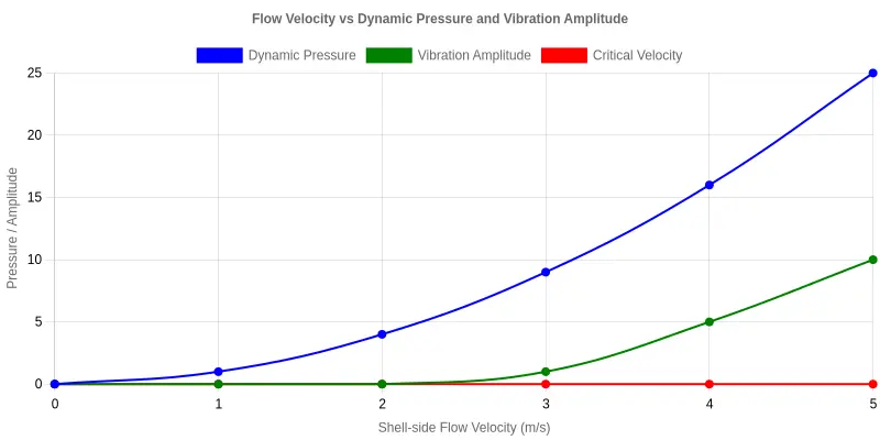
The energy that shakes a bundle comes from the moving fluid. The quantity that matters is dynamic pressure, the pressure associated with motion:
q = 0.5 x rho x v^2
where rho is fluid density and v is velocity. The exponent is the point. Dynamic pressure scales with the square of velocity, so a modest increase in velocity produces a disproportionate increase in the force on the tubes. Raise shell-side velocity by 25% and dynamic pressure rises by roughly 56%.
The Critical Velocity Threshold
Below a certain velocity, vibration stays bounded: the tube moves a little, then settles. As velocity climbs, the tube approaches the critical velocity, where fluid-elastic instability begins. At that threshold the fluid’s motion and the tube’s motion reinforce each other instead of damping out. Designers who take fatigue seriously treat the number as an operating limit rather than a suggestion.
Why Small Overshoots Trigger Self-Excited Vibration
This is where bundles surprise experienced engineers. Below the critical velocity, vibration is forced: remove the driving force and the tube stops. Cross the threshold and it becomes self-excited, drawing energy from the flow, so the vibration grows on its own. A velocity increase of just 5% above the design point can push an otherwise stable bundle into runaway amplitude. Since the energy source is self-sustaining, amplitude keeps climbing until damping, collision, or failure stops it.
How Velocity and Baffle Spacing Define the Crossflow Pattern
Shell-side velocity is not uniform. Baffles push fluid back and forth across the bundle, and baffle spacing sets the effective crossflow velocity in each window. Tighten the spacing and the flow area shrinks, raising local velocity and dynamic pressure exactly where tubes are least supported. Widen it and velocity drops, but the spans grow and natural frequencies fall. Velocity and spacing have to be tuned together.
Fatigue Life Pays the Price
Every vibration cycle flexes a tube and spends part of its fatigue life. At low amplitude the damage accumulates slowly, over decades. Once velocity drives the bundle into instability, the cycles are large and frequent, and fatigue life can drain in months instead of years. Tracking velocity, respecting the critical threshold, and coordinating both with baffle spacing is the most reliable way to keep a bundle alive.
Fatigue Life Assessment: Where Stress Amplitude Meets Cycle Count
A tube rarely fails from one violent event. It fails because thousands of small cycles add up. Fatigue life comes down to two numbers: how hard the tube is shaken (the stress amplitude) and how many times it is shaken (the cycle count). Together they decide whether a tube lasts thirty years or cracks in eighteen months.
The S-N Relationship: Amplitude vs. Cycles
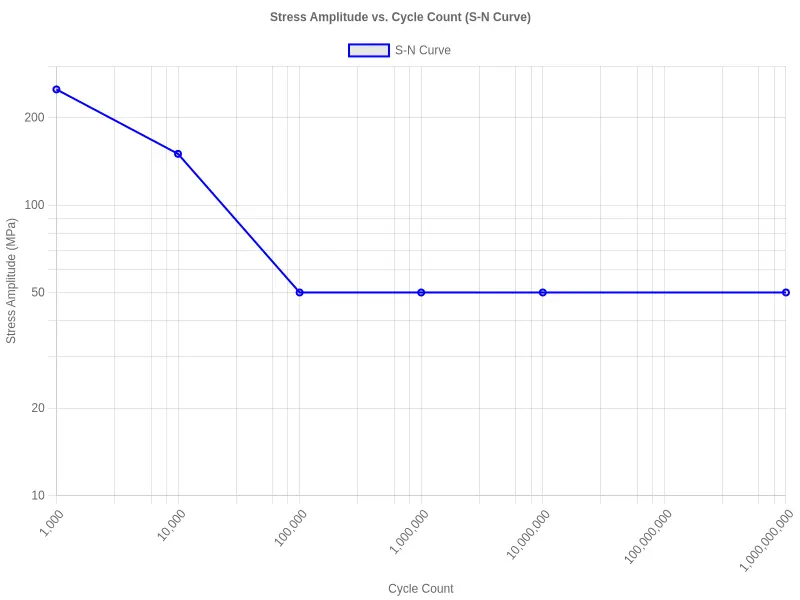
Every tube material has a stress-life curve, the S-N curve. Plot stress amplitude on the vertical axis against cycle count on the horizontal axis and the line slopes downward.
High amplitude sits at the top left, where a tube survives only a few thousand cycles. Low amplitude sits at the bottom right, where it tolerates millions or effectively infinite cycles. Below the material’s endurance limit, cycles stop doing damage.
The chart below shows the trade-off for a typical carbon steel tube.
Two Different Risks: Frequency and Amplitude
Engineers often ask which is worse, a fast vibration or a large one. They damage tubes in different ways.
High-frequency, low-amplitude vibration is common with crossflow in shell-and-tube units, and it racks up cycle count fast. A mild stress amplitude turns dangerous when it repeats 50 times per second. On the amplitude axis the curve looks safe, while the cycle count marches toward failure.
Low-frequency, high-amplitude vibration, typical of flow-induced instability or resonance, hits hard but rarely; the danger is peak stress rather than repetition. A single surge can push stress amplitude past yield and start a crack in minutes.
A tube dies from the product of stress amplitude and cycle count, so amplitude alone says little about how long it will last.
Stress Concentration: Baffle Holes and Tube-to-Tubesheet Welds
The S-N curve assumes a smooth specimen. Real tubes are not smooth, and two locations concentrate stress and shorten fatigue life:
- Baffle holes. Every rub against a baffle adds a contact-fretting notch effect, and local stress can reach two to three times the nominal value.
- Tube-to-tubesheet welds. The weld toe is a built-in stress raiser, and porosity or undercut multiplies it further.
At these points a modest bulk stress amplitude can become locally severe. Apply a stress-concentration factor when estimating fatigue life there.
Cumulative Damage Under Real Conditions
Plants rarely run at one steady condition. Flow rates ramp, startups cycle, and seasonal demand shifts the duty. Each operating block contributes its own share of damage.
Miner’s rule handles the accounting: divide each block’s actual cycle count by the allowable count at that stress amplitude, then sum the fractions. When the total reaches 1.0, the tube has used up its fatigue life.
A brief period of heavy vibration is not free; it spends fatigue budget that a quieter period cannot earn back. Track cumulative damage across the whole operating profile, not just the design point, to avoid surprises at the next turnaround.
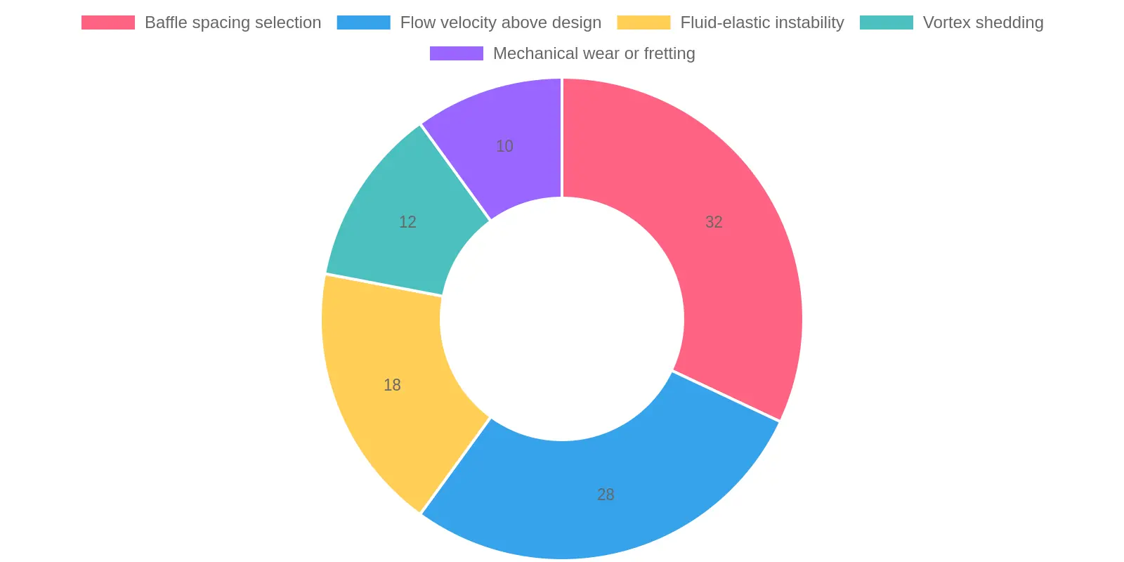
Figure: Relative contribution of design and operating factors to heat exchanger tube fatigue failure. Baffle spacing selection (32%) and flow velocity above design (28%) account for the largest share of controllable fatigue risk, which makes them the two levers engineers can most directly tune. The remaining contributors, fluid-elastic instability, vortex shedding, and mechanical wear or fretting, are largely downstream of how those first two are set.
Mitigation and Design Checklist: Engineering Out Tube Vibration
Vibration usually stays hidden until a tube has rubbed through a baffle or cracked at a support. The reliable way to extend service life is to design the excitation out from the start. The checklist below works as a screening and review sequence during detailed engineering; revisit it whenever operating conditions change.
-
Tune baffle spacing to push natural frequency out of the danger band. Shorten the spacing, or move to a hybrid layout, so the longest unsupported span stays short. Natural frequency rises sharply as span falls, which lifts the resonant frequency above the vortex-shedding and buffeting frequencies that excite the tube.
-
Set and enforce a flow velocity ceiling. Cap shell-side and tube-side velocities, or trim them by increasing flow area. Vortex-induced and fluid-elastic forces scale roughly with the square of velocity, so a modest reduction produces an outsized drop in vibration energy.
-
Place support plates wherever spans still exceed limits. Add intermediate support plates at the inlet, the U-bend, and any high-velocity regions. A support plate splits one long, flexible span into two stiffer ones, raising local stiffness without redesigning the whole baffle train.
-
Choose tube diameter and wall thickness deliberately. Specify a larger outside diameter and heavier wall where vibration risk is high. Thicker, larger tubes add mass and bending stiffness, lifting natural frequency and cutting the stress amplitude that feeds crack growth.
-
Fit vibration suppression devices in the hot spots. Install tube stakes, helical wire wraps, or damping baffles at predicted antinodes. They bleed energy out of the tube and disrupt the coherent vortex street that pumps energy back in.
-
Monitor vibration during commissioning and set a baseline. Take field measurements and compare them with predicted frequencies and amplitudes. Measured data confirms the design margin and exposes unexpected modes while there is still time to correct them, before fatigue damage accumulates.
Every item on the list comes back to the same two levers: baffle spacing and flow velocity. Get the spacing wrong and the tube ends up with a natural frequency the flow is ready to excite; let the velocity climb and you multiply the energy feeding that excitation. Supports, tube geometry, dampers, and commissioning checks all buy margin around those two decisions. Fix spacing and velocity first, and the rest of the design becomes more forgiving.
Further Reading and Reference Block
The references below document pressure and sizing data for pressure-sensitive assemblies in adjacent systems. Heat exchanger tubes and pneumatic tires do different jobs, but both depend on controlled pressure, clearance, and tolerances.
Readers comparing pressure tolerances may consult the general tire pressure calculator or the 18-inch dirt bike inner tube overview. For metric sizing examples, see the 120/70 ZR17 pressure reference and the 180/55 ZR17 pressure guide. Fleet maintenance teams can review the motorcycle TPMS fleet safety summary and the 3.50-10 scooter tire safety notes.
Each page stresses consistent units, measured values, and documented limits, which is the same discipline baffle spacing and flow velocity call for in a shell-and-tube exchanger.
Frequently Asked Questions About Heat Exchanger Tube Vibration
These come up most often when an engineer finds tube wear, leaks, or rising pressure drop in a shell-and-tube unit. Each answer stays on the two variables that decide whether a bundle survives: baffle spacing and flow velocity.
How does baffle spacing affect tube natural frequency?
Baffle spacing sets the unsupported span, and the span controls the natural frequency. Shorter spacing gives a stiffer span and a higher natural frequency, away from resonance. Wider spacing lowers the natural frequency toward the vortex-shedding and turbulence frequencies that drive heat exchanger tube vibration.
What shell-side velocity typically triggers fluid-elastic instability?
There is no universal threshold. Fluid-elastic instability generally appears when shell-side velocity crosses a critical value, often in the 3 to 6 m/s range for typical liquids and water; gases tolerate much higher velocities. That critical velocity depends on baffle spacing, tube stiffness, and support, so each exchanger needs its own analysis.
Can increasing flow velocity ever reduce vibration?
In limited cases, yes. Higher velocity can shift vortex shedding away from a resonant frequency, or change the fluid-elastic coupling so damping dominates. It also raises kinetic energy and destabilizing forces. Treat higher velocity as a fix only when a verified analysis, with defined baffle spacing, shows that amplitudes and forces actually fall.
How is tube fatigue life estimated?
Combine the tube material’s stress-cycle (S-N) curve with the vibratory stress amplitude and cycle frequency caused by heat exchanger tube vibration. Rainflow counting and Miner’s cumulative damage rule convert the alternating stresses into an estimated number of cycles to failure. Baffle spacing and flow velocity set the span and the excitation, so both enter the calculation.
What are the first signs of tube vibration damage?
Early indicators include fretted tube surfaces at baffle intersections, shiny wear flats, and fine metal debris in the shell, along with leaking tube-to-tubesheet joints, rising pressure drop, and localized thinning. They usually appear where the unsupported span is longest and the crossflow velocity is highest.
Does changing baffle spacing affect pressure drop?
Yes, significantly. Reducing baffle spacing adds more baffle windows, which typically raises shell-side pressure drop and pumping cost. Increasing it lowers pressure drop but reduces support and lowers the tube natural frequency. Baffle spacing changes both vibration risk and hydraulics, so it is always a trade-off.
Can you suppress vibration without changing baffle spacing?
Yes. Options include intermediate tube supports, no-tubes-in-window designs, tube stakes or rods, and a small reduction in shell-side velocity. Each raises natural frequency or cuts excitation energy, and combining them can keep the existing spacing while bringing vibration within acceptable limits.
Why does flow velocity matter more than tube diameter?
Flow velocity sets the energy available to excite the tubes. Raising it increases vortex-shedding forces, buffeting, and the risk of fluid-elastic instability faster than most geometry changes can offset. Tube diameter and baffle spacing affect natural frequency and damping, but without enough velocity there is no energy to cause damaging vibration.
Conclusion
Heat exchanger tube vibration is not a random nuisance but a predictable result of two design choices: baffle spacing and flow velocity. The mechanisms section followed the excitation chain, from shell-side crossflow through vortex shedding and buffeting to fluid-elastic instability. The spacing analysis showed that unsupported span sets a tube’s natural frequency and stiffness, and therefore how close the bundle sits to resonance. The velocity discussion linked crossflow speed to both excitation energy and damping, and defined the threshold where modest oscillation becomes destructive. Neither variable can be optimized alone: tightening spacing to raise stiffness also raises pressure drop, and lowering velocity to reduce excitation erodes thermal performance.
Designing for vibration integrity means treating fatigue life as an operating-envelope specification, not a single steady-state check. Evaluate the tubes against turndown, fouling, density changes, and startup transients, because a condition that looks safe at the design point can still push the bundle across an instability threshold in service. The durable exchangers are the ones where spacing and velocity margins were chosen deliberately, keeping heat exchanger tube vibration within limits from first flow to end of life.